For the final project in Machine Elements we were tasked to design and build a remote-controlled car in groups of five. These cars would then be raced against each other at the end of the semester. This project was broken into three main components that we would complete throughout the course: the chassis, drive-train, and steering. These components only served to split up the deliverables across three months; the design of the car by necessity was iterative, meaning that we had to reconsider our exisiting designs once we found something we had previously planned wouldn’t work as intented. An example of this is after we designed and cut the mounting holes into the chassis for our motor mount, we realized the size of gears means they couldn’t mesh properly. This required us to go back and re-make the chassis to have vertical mounting slots, so we could move the motor mount dynamically by loosening and tightening the screws. Additionally, we had to redesign the motor mount to also hold a shaft for an idler gear that would give us the space we needed in the drive train.
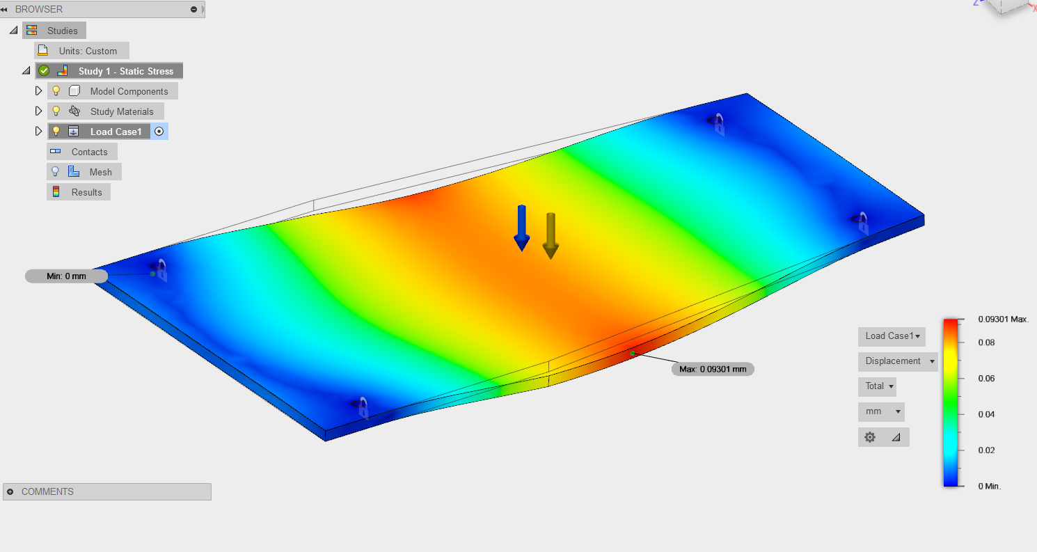
The chassis was initially made to just be a flat piece of laser-cut acrylic, which we could mount the eletrical and mechanical components to. We did a basic FEA analysis in solidworks, pictured below, which showed that for the forces we expected a single sheet of 1/8th inch acrylic would suffice. In hindsight we should have designed some multilayered design because flexure between the front and rear of the car proved to be an issue, especially where it impacted the gear box. At the time we wanted to start with something simple we could build the rest of the car around, and go back and edit if we saw any major problems. The flexure issue was insignificant enough that by the time we finished building the rest of the car we figured it hold up throughout the final race.
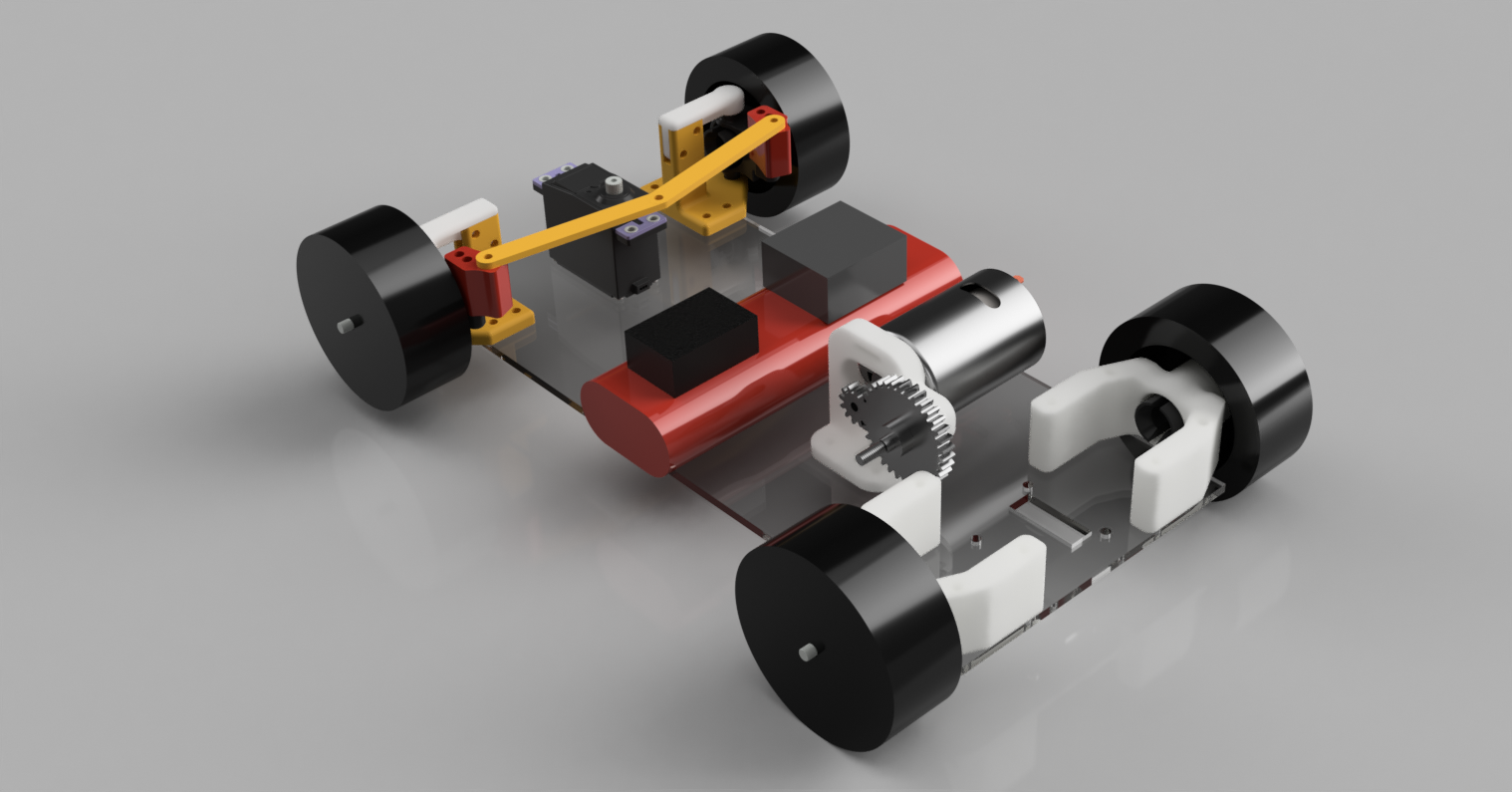
The drive-train design centered around the choice in the gear ratio. Using the rated torque-speed curve of the provided motor and assuming the coefficient of friction to be around 0.9, we estimated a desired gear ratio in the range of 3-7 between the motor and the wheels. To help give us more traction during the turns and avoid wheel slippage we chose to make a rear driven car with a rear differential. Initially we tried to 3D print the differential, but the gear teeth were so weak that we decided to purchase a composite RC differential, along with a metal pinion and idler gear. This durability ended up proving it’s worth during the race, when the groups using plastic gears found their teeth completely worn off after a few laps. We purchased standard 10th scale RC tires, dogbones, and axels, which made the rest of the drive-train design very simple. After printing two back axel mounts and an adapter for the dogbones to differential, the rear of our car was complete.
The last piece to design was the steering component, which ended up being the most straight-forward component. A bell-crank desing was chosen because of the rotational movement of the steering servo we were provided. All that we need to make were linkages to connect the axel mounts to the steering servo and a couple shoulder knuckles to set the angle of the rotation for each wheel. A simple approximation using Ackerman geometery was used to solve for the length of the linkages and the angle of the knuckles. All of these parts took less than half an hour to print, and fit perfectly on the first attempt.
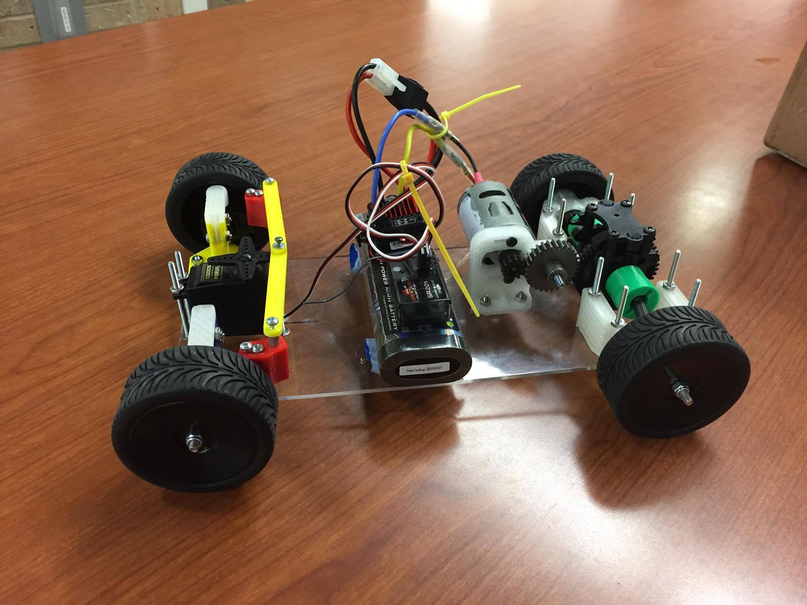
Overall our car placed first in the competition. Our final report and presentation are shown below.